December 19, 2024
Fixture design for large thin-walled bushing parts
Removal sleeve Is a thin wall bushing part of challenging machining. Market demand for these parts is huge. In the past, operators clamped the product cylindrically using three-jaw chucks or secured it by internally supporting holes for machining.
These clamping methods fail to prevent deformation during machining, leading to low product qualification, high rework rates, and reduced enterprise efficiency.
We designed and manufactured a special fixture to improve quality, reduce costs, and optimize factors like fixture, tool geometry, process plan, and program for machining thin-walled bushing parts.
This fixture reduced workpiece deformation, improved machining accuracy, and increased the qualification rate, ensuring product quality. This fixture simplifies loading and unloading, reduces auxiliary time, and boosts product efficiency.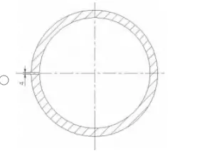
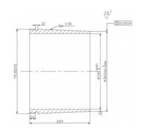
Fig. 1 Parts drawing of shunted sleeve (unit: mm)
Analysis of technical requirements and process characteristics of parts
(Unit: mm)
1. Technical requirements
( 1) Material 45# steel, tempered, hardness 229~241 HB;
( 2) No oil shank, no oil groove;
( 3) The design specifies a Tr380×5 trapezoidal male thread.
( 4) Chamfering is 2×45°, sharp angle deburring.
2. Difficulties in machining this part
( 1) thin-walled bushing parts machining deformation problems that may occur
Due to external stress, the thin-walled bushing part could develop various characteristics. For example, when external stress exceeds its load-bearing capacity, it causes elastic or plastic changes in materials. The increased cutting area temperature deforms the workpiece
( 2) To solve the problem of machining clamping positioning accuracy
Since such thin-walled bushing parts are made of 45# tempered steel with high specifications, manufacturers must take various measures to ensure processing accuracy and high productivity. A three-jaw chuck or internal support hole is commonly used, but the imbalance in holding force can cause loosening, twisting, reduced machining quality, and higher costs.
The large size specification of this part makes the difference between its stress point and the application surface of the tightening force more prominent, so operators must machine the Tr380×5 trapezoidal thread by turning. The limited rigidity of this method can cause oscillation or deflection during thread machining, shortening the thread’s service life.
( 3) The coaxially of the part tolerance requirements
To ensure coaxiality between the outer cone and the internal hole, the clamping points must be as smooth as possible. Therefore, operators need to expand the assembly space to reduce the imbalance of the clamping force. Therefore, a special fixture must be manufactured to process high-quality thin shell bushing parts.
3. fixture design of parts
Given the size of the part, which is thick, rigid, and fragile, the traditional clamping methods and processing technology have been unable to meet its high-quality requirements. To solve this problem, it is necessary to develop a set of special, effective resistance to the role of the cutting force of the special fixtures to ensure its high-quality processing.
As a complex component, the fixture requires operators to combine multiple parts closely. They must also ensure that its form, size, and accuracy meet the necessary characteristics for disassembly, considering several influencing parameters. These parameters include arranging the parts in order, designing the parts to meet appearance characteristics, achieving the required machining accuracy, selecting suitable materials, and adapting the fixture to the operating environment.
To ensure effective use of the thin-walled parts fixture, we must consider how to meet the following requirements.
( 1) The whole fixture has enough strength and rigidity.
( 2) Adopting advanced technology, the fixture should not only meet sufficient strength and rigidity but also require low weight and simple structure, so that the machine operator can quickly mount and dismount the workpiece.
( 3) Installation of the workpiece must be stable and reliable.
( 4) The size of the components to achieve a certain degree of accuracy and stability is not easy to deform.
( 5) The overall structure of the fixture technology is good, the parts are easy to manufacture, assemble, and maintain.
( 6) The fixture itself is quick and easy to clean up.
Description of the structure of the fixture
1. Structural composition of the fixture
Fig. 2 illustrates the fixture’s structural composition.
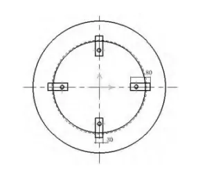
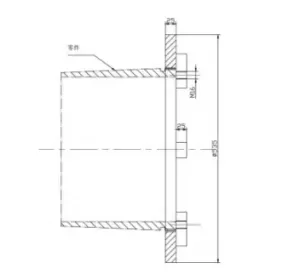
Fig. 2 Schematic diagram of fixture and workpiece mounting (unit: mm)
(1 ) fixture body, the material is 45 # steel, the outer circle size of 535 mm, thickness size of 25 mm, the boring thread for the Tr380 x5 trapezoidal thread man tool internal threads and parts of the external threads with the fit can not be too loose, to avoid turning the parts loosened, thus affecting the positioning accuracy. The fit should not be too tight either: this may affect the installation and dismantling of the workpiece).
Four fixture sub-bodies (square pins) are evenly welded around the main body. Made of 45# steel, each measures 80 mm in length, 30 mm in width, and 25 mm in thickness, with M16 threaded holes for M16x30 mm hexagon socket head cap screws.
2. The role of the hexagon socket set screws
(1) quick installation of the workpiece, when the workpiece headset is clamping, through the threads with the workpiece spinning people, tighten the hexagon socket set screws to control the parts in the processing of its X direction and the direction of the degree of freedom. The hexagon socket set screw end face protrudes from the square pin, allowing easy boring to the required length and avoiding interference with the lathe.
(2) workpiece disassembly is convenient, parts processing is completed to be unloaded, the hexagon socket set screw is loosened, and then the workpiece screw can be screwed out.
3. The use of this special clamp has specific advantages (as shown in Figure 3)
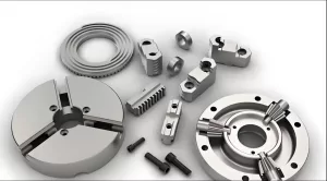
Fig. 3 Actual drawing of fixture and part assembly
The advantages of using this special fixture are as follows:
(1) This special fixture guarantees the mounting accuracy of the parts. It ensures the consistent positioning of the parts, tools, and machine tools during batch machining, thereby improving the efficiency of the entire production line.
(2) Improve the problem of clamping deformation – when clamping the workpiece with this fixture, the radial clamping is changed to axial compression, which improves the rigidity of the workpiece loading and reduces the problem of workpiece clamping deformation.
(3)By adopting this fixture, the workpiece can be easily and quickly clamped in place, and the rigidity of the workpiece can be enhanced, thus greatly improving the cutting efficiency and greatly enhancing labor productivity.
(4) Reduce production costs by installing fixtures, not only to expand the field of application of machine tools but also to achieve a more efficient and flexible operation, thus realizing a multi-functional machine. This new type of fixture not only saves money but also improves productivity.
(5)Through the use of this special fixture, not only greatly reduces the physical burden of the operator, but also ensures the stability of the clamped workpiece, but also makes the machine tool fixture workpiece between the three more solid, thus effectively preventing machining errors, to ensure that the operator and the safety of the environment in which they are located.
Advancements in technology and the use of specific fixtures reduce production costs, improve labor productivity, and lower scrap rates.In addition, as the number of workpieces processed increases, the use of specific fixtures can achieve more significant economic benefits.
Parts machining process
1. Machining steps and machining process
Fig. 2 illustrates the fixture’s structural composition.
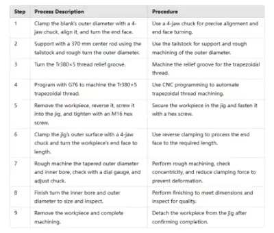
(1)Use a four-jaw chuck to hold the outer circle of the rough bed, correct the outer circle, and turn the end face.
Use the tailstock to hold a 370 mm long top bar with a center hole and roughly turn the outer circle.
(3)Turn the Tr380x5 thread backing groove.
(4) Program the Tr380x5 trapezoidal screw with the G76 instruction using the software.
thread machining with the G76 instruction.
(5)Disassemble the workpiece and screw the head into the internal thread of the fixture to make it almost flat. Then use the hexagonal wrench to tighten the M16 hexagonal screw to the workpiece plane.
(6)The use of a four-jaw counter-clamp clamping fixture-specific cylindrical surface, turning the workpiece end face to the size length.
(7)rough machining taper outer circle and bore, roughing finished with the percentage meter on the outer circle of the workpiece, and then the chuck four jaws micro-loosening under the appropriate reduction in clamping force, to avoid the workpiece fine-tuning, disassembly of the workpiece when the deformation.
(8)start fine-tuning the inner hole and outer circle to size, and test qualified.
(9)dismantle the workpiece and complete parts processing.
2. Machining process protocols
3. Precautions during machining
(1) To avoid loosening of the workpiece during the turning process and the occurrence of accidental injury, make sure that the workpiece is firmly clamped.
Coolant like kerosene reduces thermal deformation during turning, improving the machined surface.
(3)Strictly observe the safety regulations.
Conclusion
This technology effectively addresses the machining challenges of large and medium-sized thin-walled bushing parts, like poor accuracy and deformation. This technology shortens installation and adjustment time, reduces operator burden, improves production efficiency, and ensures high-quality parts, resulting in significant economic benefits. Through the improvement of jigs and fixtures and the machining process of the thin-walled bushing parts, valuable experience has been accumulated for further research on the machining of similar thin-walled parts and the formulation of a more reasonable machining process.