November 22, 2024
Process analysis of CNC turning for thread machining
Threads have the functions of connection, fastening, and adjustment and can transmit power, so they are widely used in various mechanical structures. Although there are many ways to process threads, turning still occupies a large proportion. Compared with ordinary lathes, the use of CNC lathes to process threads, their machining accuracy, and higher productivity to turn and process high-quality threads should also pay attention to the following issues.
1. Calculation method of relevant size
When using a CNC lathe to process common threads, the relevant dimensions to be determined by the final feed position of the thread cutter in the X-direction depends on the small diameter of the thread, generally through the small diameter of the thread = large diameter of the thread – 1.3P to calculate, but also through the thread parting table to determine. There are dimensions of the light bar before machining external threads, dimensions of the bottom hole before machining internal threads, etc., which are calculated as follows:
1.1 Calculation of the diameter of the light bar before machining external threads
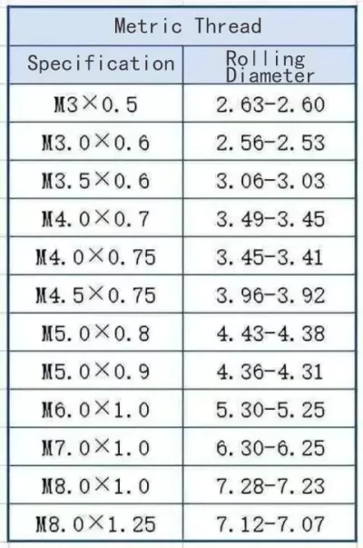
When turning external threads, if the workpiece is made of plastic material, the extrusion of the turning tool during the thread-turning process will lead to the expansion of the thread’s large diameter size, so the diameter of the light bar before turning external threads should be slightly smaller than the nominal diameter of the threads, which is generally taken as follows: diameter of the light bar=nominal diameter of the threads-(0.1~0.13)P, where P is the pitch of the threads.
1.2 Calculation of the diameter of the bottom hole before machining internal threads
When turning internal threads, the tool’s extrusion of the bottom hole during the turning process will reduce the diameter of the bottom hole. Therefore, the diameter of the bottom hole before turning the internal threads should be slightly larger than the small diameter of the threads, which is generally taken as:
(1) When the workpiece is plastic material: diameter of the bottom hole = nominal diameter -P;
(2) When the workpiece is brittle material: diameter of the bottom hole = nominal diameter – (1.05 ~ 1.1) P.

1.3 Determination of thread-cutting starting position
To avoid the phenomenon of “messy button” [2], in the cutting process of the same thread, the Z coordinate of the starting point of thread cutting should be set to a fixed value, and the setting of the Z coordinate should also take into account the introduction distance. The X coordinate of the starting point of thread cutting should be larger than the nominal diameter of the thread.
(1) Single thread. Thread cutting is generally layered cutting. To ensure that the tool can cut to the same thread, each layered cutting needs to ensure that each thread cutting starting point of the Z coordinate has the same coordinate value.
(2) Multi-thread. The Huazhong system adopts a circumferential indexing method; that is, it keeps the Z coordinate of each thread-cutting starting point unchanged and changes its position in the circumference. A thread is processed every 180° in the circumferential direction for double threads, every 120° in the circumferential direction for triple threads, and so on.
1.4 Determination of final feed position for thread cutting
The final feed position of the thread cutter in the X direction depends on the thread’s small diameter, which is generally calculated as the small diameter of the thread x the large diameter of the thread—1.3P and can also be determined by the thread parting table.
1.5 Introducing/Leading Distance
The Servo system has hysteresis; when processing threads, the starting position of thread cutting will appear “ahead” phenomenon, and the end position of thread cutting will appear “lagging” phenomenon, resulting in the processed threads at both ends of the pitch not match the processing requirements, so in the starting position of thread cutting should consider the introduction distance of the tool δ1, and in the end position of the tool should consider the introduction distance of the tool δ2. Therefore, the introduction distance δ1 of the tool should be considered at the starting position of thread cutting, and the exit distance δ2 of the tool should be considered at the end position of thread cutting. δ1=1.5P and δ2=P are generally taken as the empirical values: δ1 is 2~5 mm, and δ2 is half of δ1. For threads with a back slot structure, δ2 can generally take half of the width of the back slot.
2. Spindle speed
In thread cutting, due to the cutting force being larger, the rotational speed when turning threads should not be too high; most of the economic CNC lathe thread turning spindle speed can be based on n <1 200/P-K to determine which K is the insurance coefficient, generally taken as 80. at the same time, to ensure the pitch’s accuracy, the need to ensure that the spindle speed is constant can not be used in the G96 constant linear speed instruction.

3 Installation requirements of the thread cutter
(1) The tip of the threaded tool should be equal to the axis of the lathe spindle. Suppose the threaded tool is installed too high when cutting to a certain depth. In that case, the back face of the tool will be on top of the workpiece, resulting in increased friction, workpiece bending, and even the phenomenon of “knife”; if the threaded tool is installed too low, it is not conducive to the discharge of chips.
(2) The symmetrical center line of the threaded knife’s tip angle must be perpendicular to the workpiece’s axis; otherwise, it will lead to an incorrect thread type. The tool sample plate can help correct the threaded knife’s installation.
(3) A threaded knife head out of the length can be manageable, generally about 1.5 times the thickness of the shank. If the cutter head extends too long, the chattering of the cutter bar during processing will lead to the poor surface roughness of the thread.
4 Thread cutting feed mode
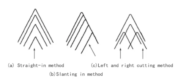
The CNC lathe processing thread has three kinds of feed methods: straight into the method, oblique into the method, and the left and right cutting method.
4.1 Straight feed method
When machining ordinary threads by the straight-in method, the thread cutter feeds intermittently along the X-axis direction (transverse) to the depth of the tooth. In the cutting process, the two cutting edges of the threading tool are always involved in cutting, resulting in a larger cutting force, difficult chip removal, poor heat dissipation conditions, and ease of wearing the tool. When the amount of feed is too large, it may also produce a “knife” phenomenon and even break the tool. Therefore, only in the tool material quality is excellent, and a small pitch (generally for the pitch P ≤ 3 mm) can be used straight into the method (G32 or G82 instruction) for processing.

4.2 Slanting method
When machining common threads by the slant feed method, the thread cutter is fed diagonally and intermittently to the depth of the thread in the direction of the tooth angle. At this time, because the threaded tool always has only a side edge involved in cutting, chip removal is relatively smooth. Still, the tool force imbalance, resulting in the spindle speed, can not be increased, and the workpiece is prone to churning, especially in the last cut, eating a more significant amount of tool, easy to produce burrs. Therefore, the oblique method is suitable for processing thread precision requirements of the workpiece is not high; if the processing of the thread precision requirements is high, to ensure that the rough and fine turning thread cutting starting position is consistent conditions, you can first use the G76 rough turning, and then use the G32 or G82 to complete the fine turning, if the rough and fine turning thread cutting starting position is inconsistent. It is easy to produce the “chaotic buckle” phenomenon. If the starting position of roughing and finishing thread cutting is not the same, producing a “messy buckle” phenomenon is easy.
4.3 Left and right cutting method
Left and right cutting method for processing ordinary threads, in the thread layering cutting process, when the end of each layer of thread cutting stroke, the next layer of thread cutting thread knife not only in the X-axis direction feed but also along the Z-axis direction toward the left and right sides to do a small amount of “lending”, this feed mode can improve the surface quality of the two sides of the tooth, due to the numerical calculations Large amount, often with the help of macro programs to complete.
5. Three common threading instructions for the (HNC-21T) system
The (HNC-21T) system commonly uses the following three thread machining methods: the single-stroke thread-cutting instruction G32, the thread-cutting single fixed-cycle instruction G82, and the thread-cutting compound-cycle instruction G76.
5.1 Single-stroke thread cutting instruction G32
Instruction format: G32 X (U) Z (W) R E P F. Instruction word description: X, Z for the absolute coordinates of the effective end point of the thread; U, W for the effective end point of the thread relative to the incremental coordinates of the starting point of thread cutting; R for the thread cutting in the direction of the Z-axis backward; E for the thread cutting in the direction of the X-axis backward; P for the main spindle reference pulse distance from the starting point of the thread cutting spindle angle; F for the thread guide.
The G32 instruction can be used to process conical threads, cylindrical threads, and face threads, both external and internal threads. When cutting threads in layers, each layer is composed of four program segments: X-axis feed (G00), Z-axis thread cutting (G32), X-axis retracting (G00), and Z-axis retracting (G00). Thus, there are many program segments written with the G32 instruction.
5.2 Thread Cutting Single Fixed Cycle Instruction G82
Instruction format: G82 X (U) Z (W) I R E C P F. Instruction word description: X (U), Z (W), R, E, F and G32 instruction X (U), Z (W), R, E, F has the same meaning; I for the thread starting point and the end of the thread of the radius difference; C for the number of threads, single-head (line) threads to take 0 or 1; P: single-head cutting threads, for the spindle reference pulse distance from the starting point of the thread When single head thread cutting, it is the Angle of spindle at the base pulse of spindle from the starting point of thread cutting (default value is 0), and when multi-head thread cutting, it is the Angle of spindle corresponding to the starting point of cutting between the neighboring thread heads. Because the G82 instruction is a fixed cycle instruction, when cutting threads in layer-by-layer processing, each layer of cutting only needs to call G82 once, which can contain four program segments when using the G32 instruction so that it can simplify the programming.
5.3 Thread Cutting Compound Cycle Instruction G76
Instruction format: G76 C(c) R(r) E(e) A(α) X(x) Z(z) I(i) K(k) U(d) V(Δdmin) Q(Δd) P(p) F(l).
Instruction word description: x, z, i, F, and G82 instructions in the X, Z, I, F have the same meaning; c for the number of finishing; r for the thread Z-axis direction of the amount of retreat; e for the thread X-axis direction of the amount of retreat; α for the tip of the Angle, according to the type of threads are generally in 80 °, 60 °, 55 °, 30 °, 29 ° and 0 ° of the six angles to choose; k for the height of threads (radius amount); Δdmin for the Minimum depth of cut (radius); Δd is the first depth of cut (radius); P is the spindle angle from the start of thread cutting at the spindle reference pulse.
When processing threads with a large lead, more cutting cycles are required, and it will become very cumbersome to program with G32 or G82. However, using the G76 instruction, only one instruction is needed to complete the layered cutting of threads.
6 .Conclusion
In the processing of threads, only through the correct size calculation, a reasonable choice of turning tools and the correct installation, a reasonable selection of the introduction/lead distance, to determine a reasonable spindle speed, and according to the material of the workpiece, the pitch of the thread and the thread of the precision requirements of the selection of a reasonable way of feeding, to ensure that the quality of the processing of threads.