May 15, 2025
Research on Five-axis CNC Machining Technology of Integral Impeller
Machining Integral Impellers for Gas Engines with Advanced CNC Technology
The integral impeller is a key part of the gas engine. It continuously compresses and outputs gas using external mechanical work. It requires low gas flow loss. It requires high efficiency. It also requires the ability to expand the stable operating and high-efficiency areas of the whole machine’s performance. The excellent shape of the impeller guarantees the performance. Multiple modifications and performance optimization after the engine test are needed to determine the number of blades and the shape profile.
Due to its complex structure and aerodynamic requirements, the processing of integral impellers has always been a difficult problem in machining. Traditional methods struggle to ensure accuracy and surface quality. The development of multi-axis linkage CNC technology has made CNC machining of integral impellers possible. However, its complexity still makes it a research hotspot in the manufacturing industry. This article will study parametric modeling. It will study the process flow. It will study automatic programming. It will study tool path generation. It will study G code. It will study actual processing verification.
1 Parametric Modeling of the Impeller
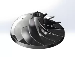
The impeller is an important complex part of aerospace. The blades have complex curves and surfaces. Therefore, this paper uses Pro/Engineer for parametric modeling and 3D design. Fitting discrete points generates the curves and surfaces. Then, solidification completes them. Copying the array completes the overall modeling and rounding. Figure 1 shows the overall impeller model.
2 Processing Technology of Integral Impeller and CAM Automatic Programming
(1) Analysis of the Processing Characteristics of the Integral Impeller
The impeller processed in this article has a diameter of 208mm. It also has a large rotation space. During processing, the consistency of the processed surface must be ensured. This ensures processing accuracy and surface quality. During processing, the cutting depth must be controlled. The processing efficiency must also be ensured.
Blade processing is difficult. The spacing between blades is small. The distortion of the blades is significant. Therefore, the tool axis swings between the two blades. This prevents interference.
The processing groove becomes narrower. The blades are relatively long. Their rigidity is low. They belong to thin-walled parts. The processing process is very easy to deform. During the processing, the deformation caused by the residual stress of the processing must be prevented.
The space between adjacent blades is extremely small. The tool diameter is small during the corner cleaning process. Therefore, the tool is easy to break. Pay attention to the selection of the tool.
(2) Processing Technology Analysis of Integral Impeller
The integral impeller used in this study has a diameter of 208 mm. It also has a height of 76 mm. It has a total of 9 sets of blades. It is made of 7075 hard aluminum alloy. The minimum size of the blade slot is 18.5 mm. The fillet between the blade and the hub is R5 mm.
According to the impeller structure and requirements, the basic processing flow is as follows:
Turn the rotating body from the forged aluminum material. Rough the flow channel and blades.
Finish the blades.
Finish the flow channels.
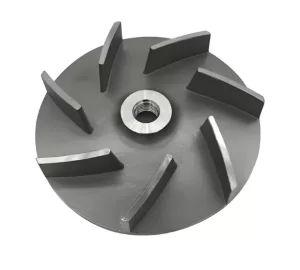
The initial blank is a bar of 215mm x 80mm. Turning it creates a milling blank. A positioning shaft or a self-centering three-jaw chuck clamps it. Figure 2 shows this.
(3) Tool Path for Integral Impeller Machining
The integral impeller usually adopts five-axis linkage CNC machining. This simplifies the processing of complex parts. Its complex spatial structure and cumbersome programming make manual programming difficult. Therefore, this paper uses UG software. This achieves automatic programming.
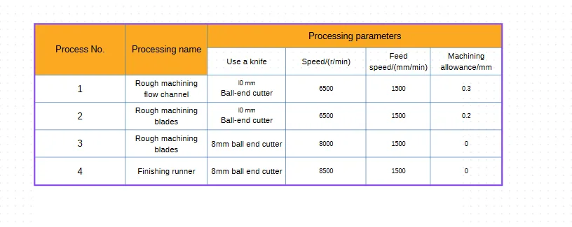
Table 1: Processing process (Note: The table was mentioned in the original text but no data was provided. This would typically outline the specific operations, tools, and parameters used in each stage of the machining process.)
3 Post-processing of a Five-Axis CNC Machining Center
UG automatic programming generates the tool path. The CNC machine cannot be used directly use it. Therefore, we need to use the post-processing of the machine tool here.
4 Processing and Verification
To verify the modeling design and process planning, we conducted cutting tests on a five-axis machining center. No overcutting occurred. No undercutting occurred. No interference occurred. This verified the correctness of the program. At the same time, we optimized the cutting parameters. After finishing, the surface roughness of the parts reached Ra0.8mm. The dimensional accuracy error reached 0.002mm. This met the design accuracy requirements.
5 Conclusion
Through the study of CNC machining of typical complex parts of aerospace, this paper obtains the following conclusions and results:
(1) Pro/Engineer completed the parametric modeling of the entire impeller.
(2) The machining process of the integral impeller was analyzed. A corresponding process plan was made. Automatic programming combined with UG software generated the corresponding tool path trajectory.
(3) The post-processing editor (NX/PostBuilder) that comes with UG created the post-processing file. The corresponding CNC machining program was generated.
(4) Actual CNC machining verified the correctness of the modeling. It also verified the feasibility of the machining process.