
August 28, 2024
What is the difference between CNC lathes and milling machines?
CNC machine tools appeared as early as the 1940s. Motors were first used to control tool movement for cutting and milling, and with advances in computer technology, CNC processing emerged.
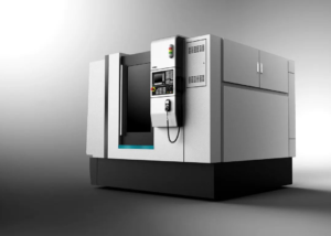
CNC machine tools divide into milling machines and lathes based on different tool directions and structural methods to meet the processing needs of various curved surfaces.
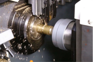
CNC lathe
The lathe is a processing method for rotating workpieces. The fixed longitudinal and horizontal tool movement processes circles and faces. It can turn axles, drill holes, process inner walls, cut threads with tool-workpiece rotation linkage, and turn irregular shapes with a larger tool.
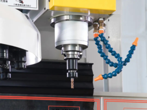
Milling machine
Milling is a machining method in which the tool rotates. The machine tool spindle clamps the part onto the three-claw chuck, and the operator mounts the workpiece on the workbench or accessories, such as a dividing head, during milling operations.The milling cutter rotates as the main motion, with feed motion from the workbench or milling head, shaping the workpiece surface. Due to multi-tool intermittent cutting, the productivity of the milling machine is higher.
How to choose a machine tool?
Lathes are most suitable for manufacturing cylindrical parts. The cross-section of the part must be circular, and the same center axis must run through its entire length.
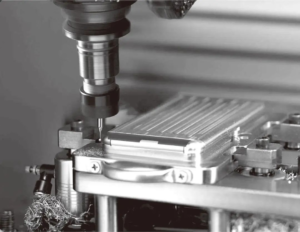
Milling machines can process cylindrical features. On milling machines, you can process planes (horizontal and vertical), grooves (keyways, T-slots, dovetail grooves, etc.), toothed parts (gears, spline shafts, sprockets, spiral surfaces (threads, spiral grooves), and various curved surfaces. In addition, it can also process the surface of rotating bodies, and inner holes, and perform cutting work.
But if the part is purely cylindrical, a lathe is a better and more accurate choice.
How does CNC machine processing work?
CNC machining starts with designing a 3D model using CAD software, where engineers adjust the part’s shape and run simulations to predict its real-world performance.
Once the CAD design is complete, it is converted into a series of instructions for the CNC machine, known as “G-code,” using CAM software.
The machine cannot understand the 3D shape on the drawing, but it can follow simple instructions to print the desired shape.
G-code contains information such as when and where the machine tools should move, how fast they should run, etc. CNC machine follows G-code instructions to remove material and shape the workpiece.
If there is no rollover, following all instructions results in a part identical to the original CAD design.
After that, you can follow this procedure repeatedly to produce parts in batches.